Choosing a Thermocouple Module is not just a matter of matching a sensor plug to a controller. The right choice depends on temperature range, required accuracy, channel count, wiring conditions, and the system receiving the readings. A module in a compact test rig may not suit a factory cabinet exposed to electrical noise. Small details matter.
Lord Kelvin, a pioneer in temperature science and measurement, wrote, “When you can measure what you are speaking about, and express it in numbers, you know something about it.” That principle is useful when comparing modules. Check how each unit handles cold-junction compensation, input isolation, sensor break detection, and calibration. These features can affect whether a reading remains dependable when the room warms, a cable runs beside a motor drive, or one channel loses contact. Specifications deserve a close look.
There is no universal best option. A high channel count may save space, yet it can complicate troubleshooting. A fast sampling rate may sound attractive, but the process itself might change slowly. Sometimes, simpler is better. This guide explains how to match module features to real operating conditions, from thermocouple type and measurement range to communications and mounting. It also points out trade-offs that are easy to overlook. One caution: published accuracy figures do not guarantee the same performance in every installation. Consider the complete measurement chain, then verify the choice against the application before ordering.
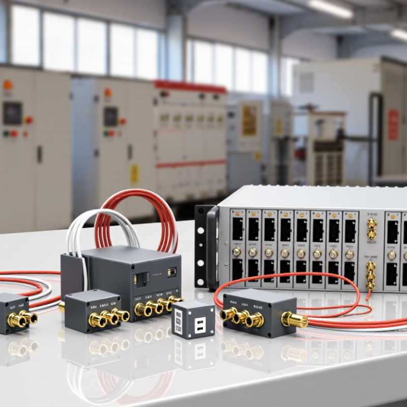
Define the measurement before comparing thermocouple modules. Record the normal operating range, expected peaks, and possible cold starts. Measure the real point. A furnace wall, moving part, and liquid pipe can have very different thermal behavior. Note the required accuracy, too, including the sensor’s tolerance and any error introduced by wiring or installation.
Response time matters when temperature changes quickly. A probe inside a thick metal sheath may respond more slowly than an exposed junction. Small details matter. Check how often the module scans each channel, especially when several sensors share one unit. A finer display can look reassuring, but extra resolution cannot correct a poorly placed probe or an unsuitable sensor type. That distinction is easy to miss.
Consider the surroundings where the module will operate. Nearby motors, long cable runs, vibration, and electrical noise may affect readings. Check that the module supports the thermocouple type and temperature range you actually use, along with cold-junction compensation and suitable input isolation. Think through channel count and future expansion, but avoid buying capacity that solves no real problem. Keep notes on the coldest point, hottest point, acceptable error, and desired response time. If those values are uncertain, measure the process under real operating conditions before selecting the module.

Choosing a thermocouple type starts with the temperatures your process actually reaches, not just the sensor’s headline limit. Type K suits many general-purpose measurements across a broad range. Type T is often useful at lower temperatures, while Type N can offer improved stability in some high-temperature applications. For very high temperatures, platinum-rhodium types may be appropriate, but they typically cost more. Check the probe’s own rating, too.
Then match the measurement range to the expected operating conditions. If a furnace normally runs near 900°C, a module range ending at 600°C will not work, even if the thermocouple itself can handle the heat. Leave room for startup peaks and process excursions. But do not choose an unnecessarily wide input range without checking the module’s resolution and accuracy. That detail matters.
Confirm that the module supports the selected thermocouple type, its linearization, and cold-junction compensation. These features affect how accurately the module converts a small voltage into a temperature reading. Also check the required temperature units and any channel-specific settings. It is easy to overlook wiring and connector compatibility when comparing specifications. I would verify the full probe-to-module setup before ordering; a technically suitable sensor can still produce unreliable readings when the measurement range or compensation settings are wrong.
Choosing a thermocouple module means matching its accuracy, resolution, and channel count to the measurement task. Accuracy describes how close a reading may be to the true temperature; resolution is the smallest change the module can show. Resolution is not accuracy. A display that changes by 0.01°C may still have larger measurement error.
IEC 60584-1 specifies Type K thermocouple tolerances of ±1.5°C or ±0.4% of temperature for Class 1, whichever is greater, across its applicable range. Class 2 permits ±2.5°C or ±0.75%. These figures describe the sensor tolerance, not the complete measurement system. Module accuracy, cold-junction compensation, wiring, and electrical noise also affect results. NIST’s ITS-90 thermocouple reference data can help verify expected temperature-to-voltage behavior. In practice, a precise-looking specification can still mislead if these sources of error are ignored.
Tips: Check accuracy across your actual operating range, not just at room temperature. For a small temperature change, compare input resolution with the sensor’s millivolt response. Count channels, too: a test bench with eight probes may need more capacity than a single-point controller. More channels, more wiring. Leave room for future sensors, but remember that spare channels do not fix a poor measurement setup.
Compare module accuracy, resolution, and channel options. Start by checking the sensor tolerance: the chart shows IEC 60584-1 Class 1 thermocouple-wire tolerance at 100°C. These are sensor tolerances, not module accuracy specifications.
When selecting a module, compare its stated measurement accuracy over your operating temperature range and include cold-junction compensation effects. Check input resolution in temperature units where available, and choose enough channels for your sensor count while confirming isolation and scan-rate requirements. Module resolution and channel options vary by model.
A thermocouple module must fit the control system, not just the sensor. Confirm the input type, channel count, connector style, and communication interface before ordering. Check whether the module supports the thermocouple type in use, such as K or J, and whether it provides cold-junction compensation. A mismatch can produce believable readings that are still wrong. Small details matter.
Isolation deserves equal attention. Review whether isolation is provided between channels, between inputs and the backplane, or both. This matters when sensors sit on equipment at different electrical potentials. In a cabinet, long unshielded leads can also collect interference from motor cables. Keep thermocouple wiring separated where possible, observe polarity, and use suitable extension wire. I would still verify the grounding plan on the actual machine; drawings do not always show every path.
Operating conditions include more than process temperature. Compare the sensor’s measurement range with the module’s supported range, then check the module’s ambient-temperature limits. A hot enclosure, vibration, moisture, or slow sampling can affect reliability or response. Think about the real installation: a sensor near a furnace may need a very different wiring route from one measuring a cool tank. It is easy to focus on accuracy specifications alone. Recheck them alongside resolution, noise performance, and expected scan rate before settling on a module.
| Selection factor | What to check | Application guidance |
|---|---|---|
| Thermocouple type | Confirm that the module supports the sensor type, such as J, K, T, E, N, R, S, or B, and the calibration standard used by the system. | The module’s configured type must match the installed thermocouple. Different types have different voltage-to-temperature relationships. |
| Measurement range | Compare the process temperature range with the module’s specified input range and the probe’s usable range. | Allow margin for start-up, excursions, and over-range conditions. Practical limits depend on probe construction, wire, insulation, and exposure time. |
| Cold-junction compensation (CJC) | Check whether CJC is built in or requires an external reference, and how the module specifies CJC accuracy. | Thermocouple measurements require reference-junction compensation. Keep input terminals away from heat sources and avoid temperature gradients across the terminal block. |
| Isolation | Review channel-to-channel and channel-to-system isolation, including the rated voltage and test conditions stated in the module datasheet. | Consider isolated inputs where sensors may sit at different ground potentials or where electrical noise could affect measurements. Isolation ratings are not interchangeable; verify the exact specification. |
| Accuracy and resolution | Check module accuracy, resolution, noise, and temperature drift across the intended operating conditions. | Evaluate total measurement error, including the thermocouple, extension wire, CJC, module, and installation. Resolution alone does not determine accuracy. |
| Wiring and input connections | Verify terminal layout, polarity, grounding recommendations, and compatibility with the required thermocouple or extension-wire grade. | Use extension or compensating wire appropriate to the thermocouple type and observe polarity. Incorrect wire or reversed connections can produce substantial errors. |
| Operating environment | Compare the module’s rated ambient temperature, humidity, vibration, and installation requirements with the control-cabinet conditions. | The module’s ambient rating is distinct from the thermocouple’s process-temperature range. Provide appropriate enclosure, ventilation, and mounting where required. |
| System compatibility | Confirm the controller or remote I/O platform, backplane, firmware, configuration software, communication interface, and supported module format. | Check the system documentation for supported hardware revisions, configuration limits, and integration requirements before installation. |
| Channel count and sampling | Estimate the number of sensor inputs, required update rate, channel scan behavior, and any filtering or averaging options. | Select enough channels for current measurements and planned expansion. Confirm that filtering and scan speed suit the process response time. |
| Diagnostics and protection | Check for open-sensor detection, over-range indication, channel status reporting, and input protection features. | Diagnostics can help identify broken wires and out-of-range readings. Confirm how faults are reported and how the control system handles them. |
Always confirm limits, accuracy, isolation ratings, and installation requirements in the selected module and sensor datasheets.
A suitable thermocouple module should match the sensor type and the temperature range your process actually uses. Check more than the accuracy listed on a specification sheet. Review the calibration certificate, its date, and the range tested; a module calibrated outside your operating range may not perform as expected. Small details matter. Confirm that the input supports the thermocouple type and provides the required cold-junction compensation.
Inspect the wiring before connecting the module. Match the positive and negative leads to the terminal markings, and use compatible thermocouple or extension wire. Polarity matters. Reversing the leads can produce readings that drift in the wrong direction. Keep sensor wiring away from motor cables and other electrical noise sources where practical. Shielding and grounding practices vary by system, so follow the module’s installation guidance rather than assuming one arrangement fits every setup.
Installation conditions can affect readings as much as the module itself. Mount it within its specified temperature limits, leave space for airflow, and secure connections against vibration. Place the sensor where it measures the process—not a nearby hot wall or a pocket of moving air. Allow for this. A quick check against a trusted reference after installation can reveal wiring or placement issues. Field conditions are rarely as tidy as a bench test, and that difference deserves attention.


